25 February 2015

Block Data Extraction in progeCAD 2016 for Simple Bill of Materials Reporting

Wikipedia defined a Bill Of Materials, BOM or product structure as "a list of the raw materials, sub-assemblies, intermediate assemblies, sub-components, parts and the quantities of each needed to manufacture an end product". Most BOMs are expected to report intelligence about materials, suppliers, part numbers and other attributes of a design's components in a way that is already specific to a certain domain, such as building or machine design or electronics, etc. AutoCAD or progeCAD, on the other hand, are seen as more general-use design standards. These programs are potentially suitable for any of those specific domains when given little extra thought from the user.

To begin with, both progeCAD and AutoCAD support the use of external and internal blocks in a drawing file. Blocks are drawings which can be re-used multiple times in another larger drawing. For example, say we use the same fastener several times in a drawing. Rather than actually drawing the same fastener detail from scratch every time it is needed in a view, our fastener block can be inserted as a reference entity everywhere we want the fastener to appear, saving both data space and drawing time. And if we have a 3D block of the fastener, we can also re-use that block again in all of different views of our drawing. Changes to the block will be reflected everywhere it is used in the drawing. Blocks also offer a great way to represent design components that we want reflected later in a bill of materials. In progeCAD 2016, internal blocks can be made "annotative" so that they scale automatically according to the annotation scale of the viewport. Custom attribute information can be inserted using the ATTDEF command while in the block's "local editing" workspace. A block's custom attributes can be viewed and edited using the BATTMAN command (for ATTEXT they need to be checked with DDATTE - see reason below).


Above is an example of using a simple three-line block defined and inserted in progeCAD, and some additional attributes which we defined using ATTDEF. NOTE: if we are inserting a lot of blocks with a lot of attributes, we can prevent progeCAD from asking us every time to confirm each attribute by setting ATTREQ to OFF. Below see the block attributes listed in BATTMAN:
 
Once we have our blocks inserted and block-attributes defined, we can generate our BOM list. There are several ways we can do this. The easiest way is to use the EATTEXT command (menu "Tools -> Data Extraction.."), choose the default settings offered and select the block attributes desired from the window that follows. progeCAD will display an export preview similar to this one: 
 
 Once we click next, we are offered a variety of output formats, including tab- or comma- separated CSV file which we can then import into a spreadsheet for final touches or incorporation into a larger existing product structure list. We can also output the attribute data to a drawing table. progeCAD has supported TABLES in DWG since version 2014.
 
Another way to generate a basic BOM in progeCAD is using the older ATTEXT command (menu "Tools -> Extract Attributes.."). Note that ATTEXT will only recognize block attributes if they were defined BEFORE the block was inserted into the drawing. EATTEXT does not have this limitation. Using this command allows you to export entity attributes using a pre-defined template file which must be created first. According to progeCAD documentation, the format for this template file is ASCII text series of single line records made of name-format pairs. Each record pair specifies a single attribute to be exported, in the order you wish the attributes to be exported. Here is a list of standard attributes:
BL:LEVEL          NFFF000   (Block nesting level)
BL:NAME           CFFF000   (Block name)
BL:X              NFFFPPP   (X coordinate of block insertion point)
BL:Y              NFFFPPP   (Y coordinate)
BL:Z              NFFFPPP   (Z coordinate)
BL:NUMBER         NFFF000   (Block counter; same for MINSERT)
BL:HANDLE         CFFF000   (Block handle; same for MINSERT)
BL:LAYER          CFFF000   (Block insertion layer name)
BL:ORIENT         NFFFPPP   (Block rotation angle)
BL:XSCALE         NFFFPPP   (X scale factor)
BL:YSCALE         NFFFPPP   (Y scale factor)
BL:ZSCALE         NFFFPPP   (Z scale factor)
BL:XEXTRUDE       NFFFPPP   (X component of block extrusion direction)
BL:YEXTRUDE       NFFFPPP   (Y component)
BL:ZEXTRUDE       NFFFPPP   (Z component)

...and this syntax is used to extract custom attribute data
'C'     literal 'C' indicating character format -or-
'N'    literal 'N' indicating numeric fields
FFF     Width of field (000 - 999)
PPP     Decimal places (.0 - .999)
0         Literal zeros - i.e. character fields have no decimals see below.
for records in the format of:
            CFFF000
            NFFFPPP

For example, to export the "DEMO-MATERIAL" attribute from our example above we would add the following record pair to our template file:
          DEMO-MATERIAL C060000
Which means "character field, maximum length 60, no decimal places"

So, to export, say, block numbers, block names, our material attribute, our cost attribute and lastly our supplier attribute for the drawing of triangle blocks used above we would write this actual template file in notepad and save as, say, "mytemplate.txt":

BL:NUMBER N010000
BL:NAME C060000
DEMO-SUPPLIER C060000
DEMO-COST C010000
DEMO-MATERIAL C060000


NOTE: Creating old ATTEXT templates is evidently a bit tricky. A faulty template file will result in 0 records extracted. It is also reported that these templates have a couple of obscure rules when used in AutoCAD. Each record must be followed by a full DOS carriage return, including the final record (so, no blank lines in between records - but a final blank line with no spaces in it). At least one custom attribute must be in the template otherwise it will silently fail. Because of these problems we recommend using EATTEXT instead of ATTEXT.

We select Comma Delimited Format option for output (this is the same as Excel's CSV file format). The results of ATTEXT in our case came out like this:
 1,'test','Demo Building Supply Pty Ltd','60','Treated Pine'
 2,'test','Demo Building Supply Pty Ltd','60','Treated Pine'
 3,'test','Demo Building Supply Pty Ltd','60','Treated Pine'


These value can be inserted into a spreadsheet or other software for processing into the final Bill Of Material.

24 February 2015

progeCAD 2016 Released with New "Dynamic" Features

Sydney, Australia 24 February 2015 - CADDIT Announces the release of progeCAD 2016 Professional CAD software. Since 2007 progeCAD has delivered the leading low-cost AutoCAD-alternative product for Australia and many other regions. progeCAD offers an affordable way to read and write AutoCAD files, using similar commands and toolbars as used in previous releases of AutoCAD itself. Many choose progeCAD over AutoCAD LT because of it's low cost (currently a little over AUD $500) and features like 3D modelling and AutoLISP which are blocked in AutoCAD LT. progeCAD is commonly used in a wide variety of industry domains, including building design, electrical and plumbing, telecommunications and fibre-optic diagrams, civil land survey, engineering, fabrication, joinery and much more. With progeCAD Professional 2016, a CAD drafter can create very large complex drawings and save directly to AutoCAD or AutoCAD LT without data loss or conversion, as shown:

DWG 2015 Test TrueView
  Left, AutoCAD 2015 DWG, Right same file read in new progeCAD 2016

Existing users who upgrade to progeCAD 2016 version will enjoy a host of new features, including dynamic input at the screen cursor, dynamic UCS for selecting 2D drawing planes on-the-fly, solid grips for editing 3D solids dynamically and support for annotative objects.

progeCAD Dynamic Input
Dynamic input allows the user to enter options and values for drawing commands via context-sensitive "tooltip" boxes and menus which appear near the graphics cursor. progeCAD dynamic input works with geometry, text and dimensions. For some users, this graphical input system seems more "user-friendly" than the traditional command prompt and use of relative polar notation.

Dynamic UCS allow users to choose a 2D planar coordinate system (UCS) merely by starting a drawing command like LINE and "hovering" over supported entities which will temporarily appear 'dashed' indicating a temporary UCS is selected. Both Dynamic Input and Dynamic UCS can be switched off at any time via their buttons on the bottom status bar.

progeCAD Annotative Detailing and Notation
Annotative Objects were introduced in AutoCAD 2008. Using Annotative Objects in progeCAD allows the user to create dimensions, text and even hatches which scale automatically scale according to the viewport or plot scale they are presented with. With more flexible detailing, drafters will not need to create as many text and dimension styles. Those which are created can be more flexible. In progeCAD, to make any supported detailing style or hatch "annotative" simply by clicking the new "Annotative" option provided.

progeCAD 2016 also offers a new ARCTEXT command with a very similar interface to the one provided by AutoCAD Express Tools. You can define text justified to an arc (not a full circle) with options on spacing, height etc. as shown here.
text along arc in progeCAD

New commands also include support for saving drawings and configurations to and from supported Cloud Storage accounts including Dropbox, Google Drive and Microsoft OneDrive. Since we now live in a time where cloud storage is more common, this new feature may prove very convenient for some users. Other new features include a new BREAKLINE command, updated icons and a larger selection of interface skins to choose from.

progeCAD 2016 Professional is available for immediate download form CADDIT. The new version will run for 30 days with all features enabled, thereafter a license must be purchased. Existing users can purchase an upgrade to progeCAD 2016 Professional from their current version. Any other questions about the new progeCAD 2016 release can be submitted on the CADDIT Contact Page.

19 February 2015

Geomagic Design 2015 (v17) Released, 32 Bit Support by Special Request

Sydney, Australia 19 February 2015 - CADDIT Announces the immediate availability of Geomagic Design 2015 V17 Release. This is somewhat a stability / bugfix release but with several new and important features requested by users in Australia and around the world. 3D Systems demonstrates its commitment to making Geomagic Design an improved tool for 3D mechanical design and drafting with this release. The most significant (and perhaps most understated) enhancement is the long-awaited Global Parameters feature. What are "global parameters"? Basically, a global parameter is a design value or equation which is shared across multiple parts and/or assemblies. The concept is very similar to SolidWorks global variables. Global variable data is stored independently in a newly released format called an ".AD_GLP" file. Any part or assembly can be associated to the values stored in an AD_GLP file.

A new set of Global Parameters can be created in Geomagic Design from the file menu -> "New" -> "Global Parameters" as shown in the Home window screenshot below:

Selecting this file type opens the new Editor interface for Global Parameters as shown. Create new parameters and save the final data as a new AD_GLP:


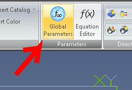
Your new Global Parameter file can thereafter be selected from any part or assembly and be used in that design by clicking the new "Global Parameters" supplied in both the Part and Assembly menu ribbons. Click "Select File" and choose your newly created AD_GLP file from the folder where it was saved to.


Other new features include: The Isolate command has been added to design instances in the Drawing Explorer. It is used to isolate a design instance in a drawing view, especially ones that are affected by an assembly feature. Standard fundamental deviations and International Tolerance (IT) grades can be selected to create Fit Tolerances on a hole and shaft, which will determine the type of fit. The dialog boxes for creating Reference Geometry have been updated to more intuitively show how reference geometry is created and to visually assist users on the various creation methods that can be used in different reference geometry creation situations. A new "Summary BOM" can now be created from an assembly. It can be used to override the Treat as part in BOM when used as a subassembly option. This is useful for quickly creating a BOM that shows all parts in subassemblies if multiple subassemblies have been set to be treated as a part.

A 32-bit version of Geomagic Design 2015 is still available but only by special request. Users should contact CADDIT for link and availability. Legacy users of Alibre Design Pro and Expert are strongly urged to renew their software maintenance subscription if they wish to take advantage or these new features and the remaining 32-bit -platform support. Subscriptions can be renewed online using this webpage: https://www.caddit.net/store/index.php?main_page=product_info&products_id=74&language=en
Google.