To begin with, download Geomagic Design HERE (link). No special settings are required at this point during the installation. Note that Geomagic Design does not support integration with Open Office. By way of overview, our example team will generate example spreadsheets which we will use to update a 3D design, which will be saved and used to update a DXF file for CNC.

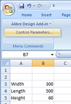 Every Geomagic Design installation includes an installation template which must be added to the Excel add-on list while running Excel once with administrator rights. Instructions as to how to do this with any supported version of Microsoft Office are available in the F1-help of Geomagic Design. Once properly installed, "Alibre Design Add-in" should be available from the Tools menu or Add-ins ribbon tab. Any numerical value cell may be selected to correspond to a Geomagic Design parameter, units specified and applied to a selected Geomagic Design file. For example we whip up something simple in Excel (shown right). Such a file can be created in Excel by anyone anywhere anytime (or it can be an imported CSV file etc)...
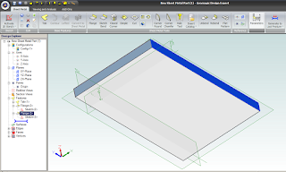
To update model parameters with the values listed in our spreadsheet, we need to start Geomagic Design and load the file in question. In our example we load the following basic Sheet Metal part, with overall parameters for "SM_length", "SM_width" and "SM_height":
Switching back over to our open spreadsheet, we select the Albre Design Add-in Control Parametrs (see above image of Excel). This opens a table in which cells are matched with parameter names:

To link spreadsheet values with model parameters, select an Active Session (model name currently open in Geomagic Design). All of the selected session's parameters will be listed by name. Now select the name of the desired model parameter from this list - and then the small "_" button down under Cell Reference and pick the workbook cell that you wish to link it to. Click the "Modify" button to finally change the parameter value to the one in the spreadsheet. Changes are shown immediately in Geomagic's active session model. Multiple changes can be made and applied at once by multi-selecting through the parameter list. If the spreadsheet is saved, the parameter links are saved with it.To generate a DXF file of the final sheet metal design, a Geomagic drawing is used. Create a new Standard View. In the open Standard View Creation window, click the button "More Options". Check the option "Project as Flat Pattern" which will use the flattened version of the Sheet metal design for the projection view. Check that the projection scale is 1:1 and create the view. Once the flattened view is created, export the version of DXF which you require for CNC.
Geomagic Design is Australia's de facto low-cost 3D CAD alternative to SolidWorks and Autodesk Inventor. For more information about Geomagic Design or a free download, visit our website at http://www.caddit.net/cad-cam-software/geomagic.php
No comments:
Post a Comment