Showing posts with label excel. Show all posts

25 February 2015

Block Data Extraction in progeCAD 2016 for Simple Bill of Materials Reporting

Wikipedia defined a Bill Of Materials, BOM or product structure as "a list of the raw materials, sub-assemblies, intermediate assemblies, sub-components, parts and the quantities of each needed to manufacture an end product". Most BOMs are expected to report intelligence about materials, suppliers, part numbers and other attributes of a design's components in a way that is already specific to a certain domain, such as building or machine design or electronics, etc. AutoCAD or progeCAD, on the other hand, are seen as more general-use design standards. These programs are potentially suitable for any of those specific domains when given little extra thought from the user.

To begin with, both progeCAD and AutoCAD support the use of external and internal blocks in a drawing file. Blocks are drawings which can be re-used multiple times in another larger drawing. For example, say we use the same fastener several times in a drawing. Rather than actually drawing the same fastener detail from scratch every time it is needed in a view, our fastener block can be inserted as a reference entity everywhere we want the fastener to appear, saving both data space and drawing time. And if we have a 3D block of the fastener, we can also re-use that block again in all of different views of our drawing. Changes to the block will be reflected everywhere it is used in the drawing. Blocks also offer a great way to represent design components that we want reflected later in a bill of materials. In progeCAD 2016, internal blocks can be made "annotative" so that they scale automatically according to the annotation scale of the viewport. Custom attribute information can be inserted using the ATTDEF command while in the block's "local editing" workspace. A block's custom attributes can be viewed and edited using the BATTMAN command (for ATTEXT they need to be checked with DDATTE - see reason below).


Above is an example of using a simple three-line block defined and inserted in progeCAD, and some additional attributes which we defined using ATTDEF. NOTE: if we are inserting a lot of blocks with a lot of attributes, we can prevent progeCAD from asking us every time to confirm each attribute by setting ATTREQ to OFF. Below see the block attributes listed in BATTMAN:
 
Once we have our blocks inserted and block-attributes defined, we can generate our BOM list. There are several ways we can do this. The easiest way is to use the EATTEXT command (menu "Tools -> Data Extraction.."), choose the default settings offered and select the block attributes desired from the window that follows. progeCAD will display an export preview similar to this one: 
 
 Once we click next, we are offered a variety of output formats, including tab- or comma- separated CSV file which we can then import into a spreadsheet for final touches or incorporation into a larger existing product structure list. We can also output the attribute data to a drawing table. progeCAD has supported TABLES in DWG since version 2014.
 
Another way to generate a basic BOM in progeCAD is using the older ATTEXT command (menu "Tools -> Extract Attributes.."). Note that ATTEXT will only recognize block attributes if they were defined BEFORE the block was inserted into the drawing. EATTEXT does not have this limitation. Using this command allows you to export entity attributes using a pre-defined template file which must be created first. According to progeCAD documentation, the format for this template file is ASCII text series of single line records made of name-format pairs. Each record pair specifies a single attribute to be exported, in the order you wish the attributes to be exported. Here is a list of standard attributes:
BL:LEVEL          NFFF000   (Block nesting level)
BL:NAME           CFFF000   (Block name)
BL:X              NFFFPPP   (X coordinate of block insertion point)
BL:Y              NFFFPPP   (Y coordinate)
BL:Z              NFFFPPP   (Z coordinate)
BL:NUMBER         NFFF000   (Block counter; same for MINSERT)
BL:HANDLE         CFFF000   (Block handle; same for MINSERT)
BL:LAYER          CFFF000   (Block insertion layer name)
BL:ORIENT         NFFFPPP   (Block rotation angle)
BL:XSCALE         NFFFPPP   (X scale factor)
BL:YSCALE         NFFFPPP   (Y scale factor)
BL:ZSCALE         NFFFPPP   (Z scale factor)
BL:XEXTRUDE       NFFFPPP   (X component of block extrusion direction)
BL:YEXTRUDE       NFFFPPP   (Y component)
BL:ZEXTRUDE       NFFFPPP   (Z component)

...and this syntax is used to extract custom attribute data
'C'     literal 'C' indicating character format -or-
'N'    literal 'N' indicating numeric fields
FFF     Width of field (000 - 999)
PPP     Decimal places (.0 - .999)
0         Literal zeros - i.e. character fields have no decimals see below.
for records in the format of:
            CFFF000
            NFFFPPP

For example, to export the "DEMO-MATERIAL" attribute from our example above we would add the following record pair to our template file:
          DEMO-MATERIAL C060000
Which means "character field, maximum length 60, no decimal places"

So, to export, say, block numbers, block names, our material attribute, our cost attribute and lastly our supplier attribute for the drawing of triangle blocks used above we would write this actual template file in notepad and save as, say, "mytemplate.txt":

BL:NUMBER N010000
BL:NAME C060000
DEMO-SUPPLIER C060000
DEMO-COST C010000
DEMO-MATERIAL C060000


NOTE: Creating old ATTEXT templates is evidently a bit tricky. A faulty template file will result in 0 records extracted. It is also reported that these templates have a couple of obscure rules when used in AutoCAD. Each record must be followed by a full DOS carriage return, including the final record (so, no blank lines in between records - but a final blank line with no spaces in it). At least one custom attribute must be in the template otherwise it will silently fail. Because of these problems we recommend using EATTEXT instead of ATTEXT.

We select Comma Delimited Format option for output (this is the same as Excel's CSV file format). The results of ATTEXT in our case came out like this:
 1,'test','Demo Building Supply Pty Ltd','60','Treated Pine'
 2,'test','Demo Building Supply Pty Ltd','60','Treated Pine'
 3,'test','Demo Building Supply Pty Ltd','60','Treated Pine'


These value can be inserted into a spreadsheet or other software for processing into the final Bill Of Material.

04 June 2013

3D CAD Sheetmetal using Excel in Geomagic Design

Geomagic Design 3D CAD (formerly Alibre Design) software from 3D Systems supports the use of Microsoft Excel files to drive design in all low-cost versions: Design Personal, Design Professional and Design Expert. Spreadsheet-driven parameters allow for company staff to specify design criteria without the use of any CAD software - only the final update need be applied using Geomagic. Microsoft Excel 2003, 2007 and 2010 are all supported in the software help documentation of Geomagic Design 2013. This article follows a simplified demonstration of setting up, linking to and executing Excel files for a sheet metal part.

To begin with, download Geomagic Design HERE (link). No special settings are required at this point during the installation. Note that Geomagic Design does not support integration with Open Office. By way of overview, our example team will generate example spreadsheets which we will use to update a 3D design, which will be saved and used to update a DXF file for CNC.
 
 
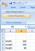
Every Geomagic Design installation includes an installation template which must be added to the Excel add-on list while running Excel once with administrator rights. Instructions as to how to do this with any supported version of Microsoft Office are available in the F1-help of Geomagic Design. Once properly installed, "Alibre Design Add-in" should be available from the Tools menu or Add-ins ribbon tab. Any numerical value cell may be selected to correspond to a Geomagic Design parameter, units specified and applied to a selected Geomagic Design file. For example we whip up something simple in Excel (shown right). Such a file can be created in Excel by anyone anywhere anytime (or it can be an imported CSV file etc)...

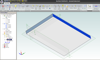
To update model parameters with the values listed in our spreadsheet, we need to start Geomagic Design and load the file in question. In our example we load the following basic Sheet Metal part, with overall parameters for "SM_length", "SM_width" and "SM_height":

 
Switching back over to our open spreadsheet, we select the Albre Design Add-in Control Parametrs (see above image of Excel). This opens a table in which cells are matched with parameter names:
 

To link spreadsheet values with model parameters, select an Active Session (model name currently open in Geomagic Design). All of the selected session's parameters will be listed by name. Now select the name of the desired model parameter from this list - and then the small "_" button down under Cell Reference and pick the workbook cell that you wish to link it to. Click the "Modify" button to finally change the parameter value to the one in the spreadsheet. Changes are shown immediately in Geomagic's active session model. Multiple changes can be made and applied at once by multi-selecting through the parameter list. If the spreadsheet is saved, the parameter links are saved with it.

To generate a DXF file of the final sheet metal design, a Geomagic drawing is used. Create a new Standard View. In the open Standard View Creation window, click the button "More Options". Check the option "Project as Flat Pattern" which will use the flattened version of the Sheet metal design for the projection view. Check that the projection scale is 1:1 and create the view. Once the flattened view is created, export the version of DXF which you require for CNC.

Geomagic Design is Australia's de facto low-cost 3D CAD alternative to SolidWorks and Autodesk Inventor. For more information about Geomagic Design or a free download, visit our website at http://www.caddit.net/cad-cam-software/geomagic.php

16 April 2012

Mathcad Prime 2.0 from CADDIT: New Excel Import, Visualization Functions

Mathcad Prime 2.0 is now available for free 30-day trial from CADDIT Australia. Mathcad offers a unique WYSIWYG whiteboard interface for scientific and engineering calculation, documentation, traceability and visualization. Mathcad Prime 2.0 is a major release in the PRIME refresh series of Mathcad from PTC. Several features have been added to the Prime Interface with this release:

  • Import data directly from Microsoft Excel spreadsheets into Mathcad. Migrate entire spreadsheets without manual data re-entry.
  • Symbolic Algebra - update polynomial equations instantly by "plugging-in" values of known variables to the worksheet. Symbolic Algebra (or so called Computer Algebra) is useful in many areas of control engineering, and provides exact calculations of procedures which may otherwise be error prone.
  • New 3D graph and plot toolbox for data visualization.
  • Collapsible Areas keep a cleaner worksheet by temporarily "folding" selected sections away from view.
  • Native 64-bit version and multi-threading options for larger calculations.
  • ... and More . .


Engineers, educators teachers & students, as well as professional in scientific or medical fields are encouraged to download Mathcad Prime 2.0 for a 30-day trial HERE. NOTE that Mathcad prices in Australia (and Worldwide) will INCREASE as of Q4 2012. Mathcad Prime users are encouraged to order their licenses BEFORE this price change. CADDIT Australia has been a local partner with PTC since 2008 and is based in Sydney, Australia. Parametric Technology Corporation is based in Needham, Massachusetts USA.

24 June 2010

Mathcad 15 Available from CADDIT Australia

Mathcad 15 is now available from CADDIT Australia. According to the official release, "Mathcad 15.0 includes over 25 new functions, more robust reference libraries and integration with third-party tools, including the latest version of Microsoft Excel. Additionally, the Mathcad 15.0 integration with existing engineering platforms like Pro/ENGINEER®, as well as with PTC’s Windchill® solutions, Windchill PDMLink® and Windchill ProductPoint®, enables better management of critical engineering content, making it easier to share and reuse information leading to standardization and best practices." More than three years have passed since Mathcad 14 was released in the beginning of 2007.

Some new features in Mathcad 15 include:
• Mathcad 15 is Windows 7 compatible (officially supported on Windows7)
Design of Experiments (DoE) – Over 25 new functions to reduce the time and expense of conducting experiments using DoE.
• Data link for the latest versions of Microsoft Excel® – Mathcad functions include READEXCEL(), WRITEEXCEL(), READFILE, an Excel data import wizard and an Excel Add-in.
• Integration to Knovel® Math content – (more information below).
• Integration with Kornucopia® software – Reduce time and effort spent on analysis by providing functions and templates using Mathcad-based documented workflows. Improves interpretations and value of experimental data and simulation results.
 
A complete product brochure for Mathcad 15 can be downloaded HERE.


Mathcad 15 license options are Individual node locked or registered user, Floating (network) and Global. Node locked licenses are fixed to a specific PC, floating licenses can each have one user at a time, by anyone on a local network (i.e. three network users all using Mathcad at the same time will need three floating licenses, etc) Schools and universities may also choose from the Student Edition, Professor Edition (node locked) and University Editions (floating). The Single User license will be effectively discontinued.

All PTC active support customers now receive:
• 24x5 technical support
• No charge access to all software updates and upgrades
• Access to the Knowledge Base which includes searchable product specific content and resources
• Discounts on product level upgrades
• Online web support and License Management tools
• “Tips and Techniques” web casts for product demos and basic training
• Gold Loyalty Program discounts with partners including Dell, Knovel, Lenovo.

In addition to the above, Mathcad customers are also entitled to:
• An additional license at no charge to be used on the Home PC of a user utilizing a network license in the office.
• Node Locked customers receive 1 Home Use License for each active license
• Floating customers receive 2 Home Use licenses for every 1 seat they maintain.
• Up to 10 Free content downloads from Knovel (more information below). Mathcad customers will particularly be interested in Knovel Math which provides fully documented Mathcad worksheets from Roarks Formulas for Stress and Strain- 7th Edition, Hicks Handbook of Civil Engineering Calculations, and the Foundation Engineering Handbook.

A new partner for updated Mathcad Extended Libraries:
With past versions, PTC Mathcad included Library Extensions for Mechanical, Civil and Electrical engineering. PTC has a new relationship with content provider Knovel, who maintain updated library extensions for Mathcad called Knovel Math. Those with Mathcad 14 can also use the old Library Extensions from that version on Mathcad 15, as well.

For more information about Mathcad 15 in Australia, contact a local partner HERE. A trial user version of Mathcad 15 is not yet ready. Mathcad 14 in Australia can still be directly downloaded from CADDIT.net HERE. Trial users from regions outside Australia should contact either their own local PTC partner or download the trial directly from PTC.
Google.