Showing posts with label design. Show all posts

08 September 2021

progeCAD 2022 Coming Soon: Free Upgrade Offer Begins


Sydney, Australia 7 September - CADDIT announces the free upgrade to 2022 version for all progeCAD purchases on or after 01 September 2021. progeCAD is a powerful general-purpose 2D and 3D CAD solution very similar to AutoCAD, with additional tools and a lower cost. With progeCAD, designers have a professional yet affordable perpetual-license alternative to high-cost AutoCAD rental fees, with the ability to create, read, write and edit native AutoCAD DWG and DXF files fluently using and interface very similar to what AutoCAD already know. Based in Sydney, CADDIT has been supporting progeCAD users in Australia, New Zealand and surrounds for more than twelve years.


Much of what will come in 2022 is still confidential but we have several detail which we can pass on now. Significant effort has been invested in making progeCAD 2022 a truly cutting-edge release that is stable and reliable from initial release. Many improvements are still confidential during an internal testing period. What we can expect are new features for the AEC industry with further improvements to BIM and REVIT compatibility, as well.  Many features are expected to be completely re-worked or refactored, such as the MTEXT and TABLE elements. Pursuant to last year's improvements in hardware acceleration, this year progeCAD 2022 release is expected to offer many new improvements in 3D view handling, modelling and new 3D content specifically targeted to architects and structural engineers working in steel. GUI customization will also be improved with several new commands.


A detailed list of these new features will be released soon, but we are delighted to share what we know now and begin offering the free upgrade to all customers. progeCAD 2021 can be downloaded now as a free 30-day trial. As in previous years, all new licenses as well as upgrades for existing licenses, including single stand-alone, floating NLM network, USB and total office licenses, purchased on or after 1 September 2021 will be entitled to the same for progeCAD 2022 upon our announcement. Multiple purchases will qualify for multiple upgrades. progeCAD Upgrades will also qualify, again as in the past. As in past, eligible users with a USB upgrade will usually not be required to replace their hardware dongle for the next version. We are really excited about the upcoming new release and making those upgrade entitlements available well in advance. So watch this space over the next weeks as more details and images become available. Contact CADDIT Australia for more information about progeCAD or this upgrade offer.

03 April 2017

CADDIT Launches Powerful Low-Cost 3D CAD Software ZW3D with Time Limited Discount Offer

Sydney, Australia 03 April 2017 - CADDIT announces an exciting new 3D CAD product line agreement with ZWSOFT to sell and support all ZW3D products Australia-wide. ZW3D offers mechanical designers, engineers, machinists and manufacturers a powerful suite of integrated CAD and CAM software for parametric 3D part and assembly design, hybrid freeform and direct editing, sheet metal nesting and weldment construction, 3D publishing and printing, prismatic and multi-axis machining, lathe turning and more. ZW3D also delivers powerful 3D CAD translation tools for importing SolidWorks, Solid Edge, Siemens NX, JT, PTC Creo, Autodesk Inventor, STEP, ACIS .sat and .sab, IGES and many more formats from even very recent versions of the software. ZW3D supplies thousands of businesses globally, including Yamaha Motor Co, Bridgestone, Johnson Controls, Baosteel and many others.

ZW3D uses specially written state-of-the-art modeling technology, originally developed by VX Corporation of Melbourne FL USA, with software R&D still located in Florida to this day. The user interface includes a modern ribbon-based UI with visual help cues and prompts. Traditional bottom-up assembly design is offered in every version of the software without limitation. Standard and higher versions also offer advanced assembly options, top-down down and animation. There are also two CAM-specialist versions for CNC machinists at reduced cost in CAD features. CADDIT also announces a special price release of ZW3D 2017 for the Australian small business user called "Workshop". ZW3D Workshop by CADDIT edition will include all features of ZW3D Premium minus the costly electrode and mould tooling libraries, to be made available at a much lower cost.


To help introduce this high-value 3D CAD and CAM software option to small business users in Australia, CADDIT has arranged for significantly reduced pricing on both software, support and one-year upgrade options. Level one support for ZW3D will be local. A series of free comprehensive one-day training events are planned around Australia, based on number of requests. The first event is planned in Parramatta NSW near our offices. Frequent news and updates will be posted over the next few weeks on  our websites. For immediate contact or general ZW3D inquiries, CADDIT.net will be the nation-wide software partner which can be contacted HERE.


24 April 2015

Important Free Update for All progeCAD 2016 Users

Sydney, Australia 24 April 2015 - An important update has been released free for all English version progeCAD 2016 Professional Single, USB and Network installations. progeCAD 2016 is a general-purpose 2D/3D DWG/DXF-native CAD, the optimum cost-effective alternative to AutoCAD® and AutoCAD LT®. progeCAD 2016 Professional reads and writes AutoCAD® DWG versions 2.5 - 2016. progeCAD 16.0.6 has been released as both an automatic update and as a fully downloadable package on the CADDIT website. The following is a non-exhaustive list of important improvements have been delivered in progeCAD 2016.0.6.6:
  • Fixed COPYCLIP between progeCAD and other software products
  • Fixed EXTRUDE of not closed polylines but with equal end and start points
  • Dynamic Input: Fixed SPACEBAR to change grip function
  • Layer Manager: Fixed creation of layer group filters
  • Removed wrong ortho glyph used with ETRACK on NWUCS
  • Dynamic Input: Fixed not allowed chars
  • Annotative Dimension: Added regeneration of annotative dimensions to avoid disappearance
  • Fixed BOX command starting from not 0 Z
  • Fixed update of angle with rotation in Z axis in VIEWCTL dialog
  • Fixed ROTATE3D X/Y/Z options in NWUCS
  • Fixed CONE/CYILINDER specify radius with Z point
  • Fixed creation of BOX by length in NWUCS
  • Fixed command WEDGE length option
  • Dynamic UCS: Fixed exception in some cases
  • Disabled OSMODE for command LOFT
  • Annotative blocks: Fixed assign of annotative scale after SAVE and re-OPEN
  • Annotative blocks: Added BLOCKSCACHE variable to disable cache of blocks
  • Annotative blocks: Fixed BLOCKSCACHE change removing automatic reload of current drawing to avoid hang
  • Annotative blocks: Added check to annotative blocks changing active annotative scale, if found pcad asks the user to disable blocks cache and reload drawing
  • Added check to avoid useless and slow set of pdf printer margin
  • Fixed JPEG printer
  • Fixed LOFT command. Now it accepts parameters from LISP
  • Fixed crash/exception saving (also autosave) drawing with thumbnail
  • Fixed save of last used path to allow to set it by external IRX
  • Fixed lisp PRINT and PRIN1 with "\\"
  • Fixed FILLET command of a closed polyline
  • Fixed FLATSHOT and implemented dragging of created blocks
  • Fixed error when autosaving a 2013 drawing
  • Dynamic Input: Fixed CONE, SPHERE, CYLINDER commands typing diameter instead of radius
  • Added new contextual menu items for viewports. "Viewport Clip", "Display Viewport Objects" and "Display Locked".
  • Command VPORTS : Fixed ON/OFF for option Lock
  • Fixed ESNAP on ACIS with NWUCS
  • Dynamic UCS: Added dynamic UCS to CONE command and direction of extrusion
  • Dynamic UCS: Added Dynamic Ucs to WEDGE command
  • Dynamic Input: Fixed NNx and NNxp annotation in ZOOM command
  • Fixed extrude command with mouse direction and esnap
  • Fixed a wrong option in the ucs menu
  • TBSIZE variable set to readonly
  • QLEADER position error (with modified ucs)
  • Fixed specify of height of CILYNDER depending from mouse direction, ESNAP or ORTHO 3d
  • Fixed specify of height of BOX depending from mouse direction, ESNAP or ORTHO 3d
  • Dynamic UCS: Fixed Cylinder command with dynamic UCS
  • Changed the saving version parameter for command line
  • Fixed freeze with files with OLE objects
  • Removed colon at the end of EasyArch object's attributes in the edit object mask
  • Cloud: Fixed save to cloud without fonts
  • Fixed INSERT command setting angle with keyboard and POLAR
  • Fixed Missing Arc Aligned Text label in QSelect
  • Fixed ROTATE command setting angle with keyboard and POLAR
  • Added some check to avoid exception in NCOPY
  • Fixed DWGPREFIX and DWGNAME variable for files in 2013 format
  • Dynamic Input: Fixed dimension pointed lines scale in imperial/metrics drawing
  • Dynamic Input: Fixed height of text in dynamic dimension in drawing if current text style has fixed height
  • Dynamic Input: Fixed FLATTEN prompt for options
  • Dynamic Input: Moved dynamic controls away from cursor position
  • Dynamic Input: Fixed prompt text of command TEXTMASK and MOCORO and various messages in express
  • Dynamic Input: Fixed display of unselected text in dynamic control
  • Dynamic Input: Fixed draw of caret in active edit control
  • Fixed Hatch of dynamic blocks
  • Fixed BREAKLINE command in NWUCS
  • Dynamic Input: Fixed PAN and ZOOM during selection in localized version
  • Dynamic Input: Fixed cursor on mandatory option list after select (PEDIT, IMAGECLIP,...)
  • Removed grips from solid face perpendicular to view direction
  • Fixed position of tooltip of ESNAP/ETRACK/POLAR
  • Dynamic Input: Fixed RAY and XLINE input
  • Dynamic Input: Fixed reset of value in GetString mode
  • Dynamic UCS: Fixed dynamic UCS during RTPAN/RTZOOM
  • Fixed the "File" menu when closed all documents
  • Dynamic Input: Fixed display of dynamic input controls after RTPAN in REVCLOUD command
  • Dynamic Input: Fixed display of selection set coordinate controls after RTPAN
  • Dynamic Input: Fixed options in RASTER commands
  • Dynamic Input: Fixed update of controls and dimensions using only keyboard
     

24 February 2015

progeCAD 2016 Released with New "Dynamic" Features

Sydney, Australia 24 February 2015 - CADDIT Announces the release of progeCAD 2016 Professional CAD software. Since 2007 progeCAD has delivered the leading low-cost AutoCAD-alternative product for Australia and many other regions. progeCAD offers an affordable way to read and write AutoCAD files, using similar commands and toolbars as used in previous releases of AutoCAD itself. Many choose progeCAD over AutoCAD LT because of it's low cost (currently a little over AUD $500) and features like 3D modelling and AutoLISP which are blocked in AutoCAD LT. progeCAD is commonly used in a wide variety of industry domains, including building design, electrical and plumbing, telecommunications and fibre-optic diagrams, civil land survey, engineering, fabrication, joinery and much more. With progeCAD Professional 2016, a CAD drafter can create very large complex drawings and save directly to AutoCAD or AutoCAD LT without data loss or conversion, as shown:

DWG 2015 Test TrueView
  Left, AutoCAD 2015 DWG, Right same file read in new progeCAD 2016

Existing users who upgrade to progeCAD 2016 version will enjoy a host of new features, including dynamic input at the screen cursor, dynamic UCS for selecting 2D drawing planes on-the-fly, solid grips for editing 3D solids dynamically and support for annotative objects.

progeCAD Dynamic Input
Dynamic input allows the user to enter options and values for drawing commands via context-sensitive "tooltip" boxes and menus which appear near the graphics cursor. progeCAD dynamic input works with geometry, text and dimensions. For some users, this graphical input system seems more "user-friendly" than the traditional command prompt and use of relative polar notation.

Dynamic UCS allow users to choose a 2D planar coordinate system (UCS) merely by starting a drawing command like LINE and "hovering" over supported entities which will temporarily appear 'dashed' indicating a temporary UCS is selected. Both Dynamic Input and Dynamic UCS can be switched off at any time via their buttons on the bottom status bar.

progeCAD Annotative Detailing and Notation
Annotative Objects were introduced in AutoCAD 2008. Using Annotative Objects in progeCAD allows the user to create dimensions, text and even hatches which scale automatically scale according to the viewport or plot scale they are presented with. With more flexible detailing, drafters will not need to create as many text and dimension styles. Those which are created can be more flexible. In progeCAD, to make any supported detailing style or hatch "annotative" simply by clicking the new "Annotative" option provided.

progeCAD 2016 also offers a new ARCTEXT command with a very similar interface to the one provided by AutoCAD Express Tools. You can define text justified to an arc (not a full circle) with options on spacing, height etc. as shown here.
text along arc in progeCAD

New commands also include support for saving drawings and configurations to and from supported Cloud Storage accounts including Dropbox, Google Drive and Microsoft OneDrive. Since we now live in a time where cloud storage is more common, this new feature may prove very convenient for some users. Other new features include a new BREAKLINE command, updated icons and a larger selection of interface skins to choose from.

progeCAD 2016 Professional is available for immediate download form CADDIT. The new version will run for 30 days with all features enabled, thereafter a license must be purchased. Existing users can purchase an upgrade to progeCAD 2016 Professional from their current version. Any other questions about the new progeCAD 2016 release can be submitted on the CADDIT Contact Page.

18 November 2014

AutoCAD Tables in progeCAD 2014 - Create and Edit

A new feature in progeCAD 2014 is comprehensive support for the AutoCAD data "table" entity set which was first introduced in AutoCAD 2005 version but improved in 2008. The data table is supported in both the full version of AutoCAD and AutoCAD LT, although the LT version does not support entity data extraction feature. It was also discussed for earlier versions of progeCAD, but had to wait for the milestone 2013 DRX-based release before it could be implemented. In a further step in AutoCAD compatibility, progeCAD 2014 can now both create new data tables and edit existing data tables from AutoCAD DWG files.

To create a new, empty data table in progeCAD, simply click either the Table icon in the Draw toolbar
, OR select "Draw" -> "Table" form the progeCAD menu. The following familiar dialogue box will appear:

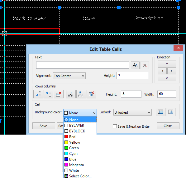
Simply specify the desired number or rows and columns, pick a size for these and set the cell styles. For now we will leave the Insert options as "Start from empty table". Then you can locate the new data table either by a single point, or cross-corner and allow the cell sizes to emerge as a calculated value. Once the table is inserted into your drawing, you can begin entering data, such as naming the headers or inserting values. This is done simply by double-clicking into one of the cells much like we would in Excel. This highlights the selected cell in red and opens up the cell's entry box:

Note that from here we can easily control many aspects of the individual data cell, like background colour, text height and much more. Text itself can be entered directly here, or formatted in the MTEXT window which can be called up by clicking the "Double AA" icon to the right of the text field.

progeCAD tables also support entity data extraction to a new table, something only supported in the full version of AutoCAD and not in AutoCAD LT. To do this we select the "from object in the drawing" insert option instead. Afterwards we are prompted to select the entities from which we want to extract the data and a template as well, if desired.

progeCAD 2014 also supports an insert from CSV file option as well.

progeCAD is a popular AutoCAD alternative in Australia because of it's low cost, local support and large community of users. For more information on progeCAD 2014 or for a free, no-obligation trial version to test for yourself, visit the progeCAD Australia webpage or contact us at our Parramatta training office.


03 June 2014

Review of New Features and Licensing for Geomagic Design V16 (2015)

Sydney, Australia 30 May 2014 - CADDIT is happy to announce the first steps of integration to the new licensing for Geomagic Design and other 3D Systems software products including Geomagic Freeform. Geomagic Design is the de facto low cost 3D CAD solution for parametric mechanical CAD design. A few weeks earlier, a significant update was released to Geomagic Design support subscribers which made several significant adjustments in the product:

Operating Systems - Geomagic Design continues to support 32 and 64-bit operating systems:
  • Windows Vista
  • Windows 7
  • Windows 8
  • Requires Graphics Card with DirectX 9.0c or above and 32 bit true color
  • Windows XP is now unsupported by Microsoft and officially unsupported by 3D Systems. CADDIT can therefore provide general information on software usage as long as the question is not XP-specific.
Import wireframe mesh as CAD solid (new):
  • Geomagic Design, Geomagic Freeform and Geomagic Studio include proprietary "autosurfacing" libraries which can convert mesh models to solids. This revolutionary, one-of a kind technology has been simplified for inclusion into the low-cost Geomagic Design software.
  • There are two options in the Geomagic Design wizard-driven version: import as "organic shape" or import as "mechanical shape". These options use different algorithms to compute NURBS curves to represent the imported mesh, one with stricter planar/arc based "feature" recognition and one suited for non-parametric freeform topologies. Import as "organic shape" will also allow the user to merge the imported shape with an opened CAD part file.
wireframe mesh STL OBJ to NURBS solid model conversion
 
 
TeamPlatorm integration:
  • Designers may now sign in directly to 3D Systems cloud storage from within Geomagic Design and share models and designs electronically.
Geomagic Design Viewer Mode:
  • A new Geomagic CAD viewer has been implemented. The CAD viewer allows users to open and view native Geomagic Design and Elements files as well as DWG and DXF files. In addition, users will be able to take measurements, obtain physical properties of a design and use the Redline tools for markups. Files can then be saved or uploaded/downloaded from TeamPlatform.
Flexnet Licensing:
  • Perhaps most importantly, Geomagic Design has incorporated a new licensing tool which will allow users to directly manage the activation and deactivation of software licenses. Geomagic Design no longer connects to Alibre CRM for license updates and can be moved ad-hoc by the user themselves. There are several licensing options now available including live floating network, virtual USB and physical USB dongles. These licenses options can be reviewed by opening the Geomagic "GSLicenseUtil.exe" directly or calling it from the main menu -> Help -> About Geomagic Design -> "License Key Status" button:
 
 
This new license system incorporates the use of serial codes issued from 3D Systems. Please note that we are finishing our migration to this system license deliveries may experience a short delay. CADDIT staff are very excited about these new features in Geomagic Design as they reflect a great deal of investment from 3D Systems to unify their software product portfolio and add value for the end-user.
 
Geomagic Design is available in Australia through CADDIT, and we invite users to test drive the new version. Download and test drive Geomagic Design V16 HERE (note you may need to rename the downloaded adding an .exe extension to run it). Even if users have tried a previous version they can still download and trial the new V16 version without any extension requests to us (unlike before). Form more information about Geomagic Design in Australia contact CADDIT.


20 February 2014

progeCAD 2014 Released on CADDIT.net - Update Information and More.

Sydney, Australia 18 February 2014 - CADDIT announces the completed initial release of progeCAD 2014 to Australia and New Zealand customers. progeCAD is the region's de facto choice for low-cost AutoCAD-compatible design software, and progeCAD 2014 is definitely the most advanced release ever. With the initial milestone of complete rewriting and refactoring finished in 2013, progeCAD 2014 was free to explore important features long requested by our users:
  • AutoCAD table entity creation and support for DWG files with data tables
  • Massive improvements in 3D - including functional ACIS sweep command and a full range of 3D architectural design tools.
  • 3D PDF Publishing included free for sharing 3D designs.
  • Initial support for Dynamic Blocks. progeCAD now attempts to present dynamic block data from AutoCAD DWG files using the grips interface. This support is still under development.
  • progeCAD now offers a full interface for creating new multi-line styles.
  • Improved support for various graphic cards.
  • Command line auto-completion mode (DYNMODE).
  • Hundreds of other improvements and enhancements.


CADDIT will begin processing iCARE and promotional upgrade entitlements this week. Users will be notified via email of their new progeCAD 2014 (English version) serial code. Please note that a 2013 serial code will not work with progeCAD 2014. Please also note that the progeCAD Standard product is no longer available. Other users who wish to upgrade from a previous progeCAD version may do so here.

A completely new 30-day trial of progeCAD 2014 can now be immediately downloaded from www.caddit.net. CADDIT is the major supplier of progeCAD to Australia, New Zealand and Asia-Pacific region since 2007. We are proud of our now very large community of users in ANZ and hope that this new release demonstrates our desire to help deliver the features requested by these users. CADDIT was directly involved with some of the new features in version 2014 and can be contacted via the website details as usual, http://www.caddit.net/store/index.php?main_page=contact_us .

17 July 2013

Geomagic Design 2014 Released on CADDIT.net with new Motion and FEA Options

Sydney Australia - Geomagic Design 2014 has been released on CADDIT Australia. One central aspect to this update is name change for all of the package levels as follows:

Geomagic Design Personal Edition is now Cubify Design
Geomagic Design Professional is now Geomagic Design ELEMENTS
Geomagic Design Expert is now Geomagic Design

This will take a little getting used to for some of us, so CADDIT continues to maintain the comparison chart on their website regarding the differences between these package levels. Also released with Geomagic Design 2014 is an extra, optional upgrade to Motion 2.0 called Alibre Dynamics and an FEA option called Simulate. The Dynamics package has been released at a very affordable cost for existing and new full Geomagic Design users under active subscription. Cubify and Design ELEMENTS users will have to upgrade to the top level Geomagic Design first before qualifying for the discounted Dynamics package.

Geomagic Design Dynamics - fantastic motion studies at low cost for Geomagic Design users on active subscription. Cubify and ELEMENT user will need to upgrade to Geomagic Design first.

Also announced was a new FEA (Finite Element Analysis) option called Simulate which extends the motion dynamics package with full 3D FEA in a unified interface for both motion simulation and finite element analysis studies. Study types include stress/strain, vibrational, thermal, etc. Use of powerful combined dynamics/FEA simulation allows for joint forces from the motion to be converted to distributed loads, inertial information is transferred into the FEA model and stress, and strain which can be re-calculated at every step of the simulation. Both packages include full comprehensive help and tutorials and can open ACIS solid models directly. Both packages are very user-friendly.


Geomagic Design 2014 also includes dozens of small fixes and enhancements in the base product of the software so any user under active subscription will benefit - but for the simulation software users will need to be using the latest version of Geomagic Design (not Cubify or ELEMENT) and pay the option fee(s). All prices for these options are listed in AUD on CADDIT.net HERE.
 
For more information about Geomagic Design 2014 or for a trial, visit us at: http://www.caddit.net/cad-cam-software/geomagic.php

16 July 2013

Bright Future for Geomagic Design Users at First APAC 3D Systems Geomagic Meeting

9 July 2013 - The first 3D Systems Geomagic annual APAC meeting was held in Bangkok, Thailand. A broad range of training and information seminars were also conducted with a peak total attendance of more than eighty from the entire Asia-Pacific region including China, Korea, India, Malaysia and Australia. Ben Decker from CADDIT Australia attended this meeting for all three days, and met and shared experience with industry professionals in scanning, reverse engineering and 3D printing. An important take away from day one is the key role that Geomagic Design (formerly Alibre) will continue to have in software development at 3D Systems. This was confirmed in the same week when 3D Systems released a new simulation/FEA add-on option for Geomagic Design Expert, with other enhancements coming soon.

All in attendance discuss future vision of Geomagic

A future vision was shared of a full 3D rapid development process, including 3D scanning, reverse engineering, design, documentation, prototyping, verification, manufacturing and testing - of which Geomagic Design will play a central role. Also discussed was integration between individual solutions of the Geomagic product family and a new Geomagic Designer bundle which includes Geomagic Freeform and Geomagic Design. Australia users who have interest in Geomagic Designer should contact CADDIT Australia or 3D Systems directly.

A rainy but comfortable Bangkok for the meeting.

18 May 2013

Geomagic Design 2013 Released on CADDIT Australia

CADDIT Australia has released the latest version of Geomagic Design 2013 (formerly called Alibre, now owned by 3D Systems). Geomagic Design 2013 is the most significant release since 2009, featuring hundreds of enhancements, improvements and fixes.

The base price of Geomagic Design remains at a modest $220. Geomagic Design is Australia's de facto choice for low-cost 3D parametric, mechanical design software which offers features similar to AutoCAD Inventor, SolidWorks and Solid Edge at a fraction of the cost. All versions of Geomagic Design includes advanced STL file export for 3D printing and rapid prototyping.

Geomagic Design Professional continues to offer photo-realistic rendering, STEP import/export and full 2D detail drawing. Geomagic Design Expert adds comprehensive sheet metal, direct (non-parametric) modeling, variant design and motion simulation capabilities. Geomagic Design Expert also offers reading of SolidWorks sldprt and sldasm files, Solid Edge and AutoCAD Inventor files. GeoMagic Exchange is a lower cost option available specific for CAD translation.

A full 30-day free trial of Geomagic Design can be downloaded from CADDIT Australia at this link:
http://www.caddit.net/cad-cam-software/geomagic.php

17 July 2012

Fast Architectural Drawing: progeCAD's Free 'EasyArch'

progeCAD 2011 is a low-cost AutoCAD alternative which supports direct reading and writing of complex detail drawings in AutoCAD's '.dwg' file format. The latest progeCAD Professional 2011 release includes several significant features over previous versions. This article explores just one of these new features: progeCAD 2011 Professional's  new "EasyArch" add-on for 2D architectural on-the-fly drawing of walls, doors, stairs and more. EasyArch architectural objects are also parametric, allowing most parameters to be conveniently redefined via dialog boxes at a later time.

EasyArch offers the fast 2D creation of:
  • Walls
  • Doors
  • Windows
  • Glass Walls
  • Staircases
  • Basic Furnishings & More
EasyArch objects can be quickly drawn by selecting the desired item from the "EasyArch" pulldown menu in progeCAD, or enabling any of its several floating toolbars. Object preferences, including text and dimension preferences can also be changed:


The Draw Walls function allows you to specify the thickness (or width) of your wall disregarding the initial and final thickness as it seems to only change to equal each other. You can choose your justification of your drawing line of your wall bearing in mind the width of your wall and the sizing when it comes to the corner. At the corner, progeCAD automatically generates the next lines coming off the corner of the wall taking into account the width and justification of the drawing line. The command line features many helpful functions for your wall including:
  • Arc (A): defines an arc for your wall with input angle.
  • Closing (C): completes the wall automatically for you when progeCAD can recognize the opportunity to.
  • Header (H): closes the last drawn length of wall much like a niche.
  • Triangle (T): creates a triangular wall partition for you.
Windows and glass walls can be added as architectural blocks to and existing wall or even line with much ease. Available windows include generic windows, glass walls and French windows. The software asks for the:
  • Width: how wide the window will be.
  • Opening Frame Distance: where the frame is located in the wall.
  • Height: of the window (3D only).
  • Angle: Direction of window frame outwards.
  • Windowsill projection: the measurement of definition of the windowsill.
EasyArch also offers a curved opening tool allowing the opening to be placed on a curved wall. Each available curved opening is the same as the generic ones available. EasyArch incorporates staircases into the list of available architectural blocks for customization and dimension editing. The available blocks of stairs include spiral-helical, corner step, flights and angle flight staircases. All required variables are asked for in the command line upon creation:


To download a free 30-day trial for progeCAD Professional including EasyArch, see the CADDIT webpage HERE. For a more complete overview of EasyArch for progeCAD 2011 Pro download this FREE PDF E-Book HERE. CADDIT is based in Sydney, Australia and has been supporting progeCAD users since 2007.

06 March 2011

iCADmac "CAD for Mac" Released on CADDIT

CAD on MAC OS/X (Version 10 or 'X' of the Apple operating System) is back. AutoCAD for Mac was (re)announced in August 2010. However, the cost of AutoCAD on Mac (several thousand dollars) makes this new option unviable for some small business looking for CAD software for Mac. As a low cost alternative to more expensive CAD on Mac systems, CADDIT will begin to offer the iCADMac product line from progeSOFT.

iCADMac "CAD for Mac" features include:

  • Native Mac OS/X CAD software - no Boot Camp, VMware Fusion or Parallels virtualization required.
  • Similar user interface to what some CAD for Mac users are already accustomed.
  • Read and Write AutoCAD .dwg CAD files, edit and print.
  • Convert PDF in to CAD / Print to PDF out from CAD
  • Raster image modification tools for use in CAD drawings
  • 3D solid modeling using the same ACIS libraries as licensed by AutoCAD
  • Table and cell support used for bills of materials, component lists and more.
  • Advanced interface for gradient hatching, entity property bar etc
  • ALE symbol library including ready 15.000 Blocks for use in your drawing
  • AutoLISP and ODA DRX C++ programming support
  • Permanent perpetual license
  • 12 Months free upgrade maintenance with new license with option to renew

CADDIT will be offering an AUD$175 discount to RRP pricing until 22 April. Architects, engineers, technicians and other CAD users looking for "CAD for Mac" will also enjoy free upgrades to additional functionality released in the iCADMac product for 12 months from the date of purchase. iCADmac can be downloaded for a free for a 30 day trial HERE. Questions about iCADMac in Australia and New Zealand should be directed to CADDIT here.

Note for Windows users - those looking for a reliable, low-cost 2D / 3D design solution on Microsoft Windows should download progeCAD for Windows HERE.

22 November 2010

Alibre 2011 Update with New MoI Surfacing Software

Alibre Design 2011 was first released in late 2010 offering a number of important new features:
  • Alibre's first native 64-bit version
  • New "in-place editing" UI framework
  • New MIRROR and SCALE modelling commands
  • On-the-fly library creation
  • Direct 3D Solid->SheetMetal conversion

MoI:
In addition to these new features, Alibre Design Expert user licenses sold after 2 December 2010 are now entitled to get MoI - Moment of Inspiration - freeform surfacing software. At this point the best link between MoI and Alibre itself seems to be using STEP data, although ACIS SAT and IGES are also offered by MoI (the IGES interface seemed to loose the most data in our lab test, but we were expecting that). One major advantage MoI offers is a "point-and-click" workflow that doesn't require use of special ALT-key combinations, which makes it perhaps more practical for use on tablet PCs.


KeyShot for Alibre:
"KeyShot for Alibre - Basic" is new realtime photorealistic rendering software offered with
Alibre Design Professional and Alibre Design Expert. The updated capabilities of KeyShot for Alibre (formerly "KeyShot for CAD") are outlined in this brochure, and summarized in the chart provided below:

KeyShot for Alibre Edition Basic (shipped w/ Pro & Expert)KeyShot for Alibre Edition (optional)
Max Real-time Resolution 1024x768 pixels 1920x1080 pixels
Max Non Real-time Resolution N/A 2500x1600 pixels
Render with alpha channel No Yes
Extra Control over Render settings No Yes

It is worth noting that, although Alibre Design is now available as a native AMD64 bit application (Windows 7 compatible) many of the Alibre add-ons such as Alibre CAM and Alibre Motion are not yet. The 32-bit version Alibre add-ons will not work with Alibre 64-bit software and require Alibre 32-bit to install and run. However there seems little problem in running Alibre 32-bit version on a 64-bit PC now. Since the first major release of Alibre's latest version of their easy-to-use 3D CAD system, a few minor bugfix updates have also been made available and the latest version of Alibre can be downloaded HERE.

30 October 2010

PTC Creo Announced for Project Lightning

Parametric Technology Corporation announced "creo, a PTC Product" at the at the Park Plaza Castle in Boston USA last week. "creo" is the name given to the overall design platform of PTC product development tools for "the next twenty years". According to PTC CEO Jim Heppelmann, creo "is the Latin root of the word create and... means I think, I create, I believe". Creo is slated as successor to the long-successful Pro/ENGINEER product line.

The new PTC Creo design platform is more than a new CAD program. Creo is a completely redeveloped design software framework that delivers a seamless and uniform design interface for modelling, drawing, simulation, detailing, manufacturing and other applications. Creo will accomplish this by means of a common data model capable of merging design information in from multiple design modes - not just parametric. With Creo, PTC answers four ongoing pain issues widespread in product development industries today:

  1. Ease of use for casual users and non-CAD personell
  2. Interoperability to use CAD files from any given CAD program
  3. Switching costs caused by migrating data from other CAD software
  4. high-level configuration driven design with multiple variations

PTC Creo will answer these problems respectively via the four cornerstone technologies upon which new Creo applications are built:

  • AnyRole Apps - scalable, easy and "role specific" applications for all types of users
  • AnyMode Modeling - seamless data portability across multiple CAD drawing modes
  • AnyData Adoption - enables direct CAD file editing in Creo from any CAD system
  • AnyBOM Assembly - drive 3D CAD assembly configurations using Windchill PLM - watch THIS...


The full event can be watched HERE. What I find interesting about AnyMode Assembly is PTC's departure from today's typical large-CAD business rhetoric, insisting that all CAD users are best served using in-depth 3D design mode tools. In observation, Brian Shepherd Executive Vice President, PTC Product Development stated "some users... are best served working in a 2D mode." He went on to say "We don't need a religious zeal around converting from one mode to another. We're about any mode."

PTC has an initial release target of summer 2011 for the new "Creo, a PTC product". CAD users are encouraged to keep their PTC maintenance current and active, so as to be in best position to enjoy these new technologies when they are released. For more information in Australia about either PTC Pro/ENGINEER or next year's new Creo platform, feel free to contact CADDIT here.

28 September 2010

progeCAD Free to Schools

progeCAD is a powerful but low-cost architectural or mechanical design package, somewhat similar to AutoCAD from Autodesk. progeCAD features include Autodesk's DWG format read/write for all versions of AutoCAD from 2010 and as far back as R11. Most of the basic commands are the same, workflow and interface all follow a similar logic. For years CADDIT Australia has been offering progeCAD Professional annual licenses to schools free of charge. One school in the New South Wales TAFE system wrote of progeCAD:

I personally consider that your company’s provision of this program for academic purposes, free of charge is the best thing that has happened to the CAD industry for a long time... I teach across a number of campuses in the Hunter and am trying to convince other sections to switch over from AutoCAD to ProgeCAD for teaching purposes. The benefits of allowing students to download the program and develop their skills at home at no cost cannot be underestimated, apart from the ethical aspect of positively discouraging the use of pirated AutoCAD software.

CSTC in Queensland Australia writes:


It is an exceptional program in the standards it allows students to apply to drawing - variety of linetypes, lineweights, hatchs patterns etc. We are enjoying using it, our trainees and apprentices appear to like the feel of it. Great program.

A few of CADDIT's academic program subscribers are from outside Australia. One school from overseas writes:

Since we only have a single, one-semester course that uses CAD, this offer CADDIT makes to license ProgeCAD to schools at no charge is a wonderful effort supporting education. Our students are able to gain experience with professional software and several have applied these skills in internships and subsequent educational experiences in vocational/technical programs and college. Without ProgeCAD's support, we would be forced to use some consumer-level software, as it would be extremely difficult to justify spending thousands of dollars to license professional CAD software for a lab that will be used with a single class of students.

Another student used the opportunity to submit a new concept for a local highway intersection to local planning authorities..
progeCAD can be downloaded free of cost HERE. For more information about how progeCAD can be used in your school, visit http://www.caddit.net/progecad/educational.php

19 August 2010

Alibre Design 2011 - New Features

Alibre Design is one of Australia's most affordable mid-range 3d mechanical CAD solutions. Within the next several weeks Alibre 2011 is expected for release. This major release both adds new features as well as improving many existing ones. A crucial focus for Alibre Design 2011 has been improvement in efficiency and ease of use, including fully customizable keymaps and in-place editing. Developers may also be interested to know that much of Alibre is now written in the Microsoft C# programming language, which allows developers to add new features even faster than before. Here are a few of the many feature enhancements of the new Alibre 2011 version release:

Alibre Design 2011 will offer Alibre's first native 64-bit version, which basically means you can make larger, more complex assemblies and have more files open simultaneously, without the restrictions of older 32-bit operating systems and memory access. With the offering of a
64 bit version comes a tremendous increase in both what can be created in Alibre Design and the types of workflows people can use. Both Alibre Design Professional and Expert versions will be offered as 64-bit editions.

Direct 3D Solid->SheetMetal conversion will allow CAD designers to take ordinary 3d solid models or imported 3D files (like STEP or Parasolid) and automatically convert these into sheet metal parts that can be flattened and machined in Alibre CAM. Of course, the resulting sheet metal parts are fully associative to their original counterparts, so that if you change the original model, the associated sheet metal version will update automatically. The new solid to sheet metal conversion tool will only be offered with Alibre Design Expert edition.


Alibre Design 2011 will add new MIRROR and SCALE modelling commands. Alibre 2011 will offer a new "Double Intersect" sketch command that allows you to join two figures at their theoretical intersection. The tool has several modes, all completely transparent to you, which adapts to the types of figures and orientations that a designer encounters. Alibre 2011 will also make it possible to create libraries of your most commonly used hole types on the fly. Simply fill out the form, type a name, and press Create. The hole's parameters can now be recalled instantly via the Presets dropdown. Alibre 2011 will also offer a new multi-plane creation tool, which can be useful when drawing multiple solid loft profiles, etc.

Alibre will begin rolling out their new "in-place editing" UI framework with Alibre Design 2011. In-place editing takes floating toolbars and context menus much further by opening relevant toolbars and icons just by selecting entities. Any changes are immediately displayed in real time, and to close in-place editing toolbars, we simply move the mouse away from the entity we initially selected. Alibre Design 2011 will offer this framework first in its Detailed Drawing Workspace, but is eventually to be deployed in various forms throughout the product.

Until release, CADDIT will begin offering free upgrades to all new Alibre Design Expert users a free upgrade to Alibre Design Expert 2011 upon release - but while still at current sale prices for V12.1. Alibre is suitable for a wide variety of mechanical design projects, including machine design, fixture design, vehicle and product development, sheet metal products and more. A free full-version trial of the current
Alibre Design software in Australia can be downloaded here. For further questions about Alibre products, CADDIT support can be contacted HERE.
Google.