Showing posts with label spreadsheet. Show all posts

09 March 2017

Mathcad Prime 4.0 Released on CADDIT

Sydney, Australia 08 March 2017 - CADDIT announces the immediate availability of Mathcad Prime 4.0 on the CADDIT.net website. Mathcad is computational software which solves equations written in conventional textbook format, as opposed to obscure expression languages used in spreadsheets. Mathcad is the application of choice for many math-critical industries, such as mining, aerospace, chemical and laboratory research environments. Mathcad updates solutions in real time, and can also be used to visualize datasets in both 2D and 3D plots. Mathcad Prime 4.0 adds several important usability features requested by our users.

PTC Mathcad Prime 4.0 extends access control features to individual worksheet areas. Using the new Area Protection and Locking functionality in PTC Mathcad Prime 4.0, users may select specific areas of a document for password protection, making them unavailable or just read-only for other users while leaving remaining areas fully editable. This feature further protects the integrity of corporate calculations, preventing protected values from unwanted alteration.

PTC Mathcad Prime 4.0 improves document readability with enhanced equation wrapping. Equation wrapping works much like word wrapping does for a text editor. Users can now both insert a wrapped addition, subtraction, multiplication or inline division operator while typing an equation (in other words, they can wrap as they go) or they can go back to existing math and toggle the wrapping on those operators too. Wrapping does not break logic linkage to the next line, and can also be inserted as the equation is typed. Improved support for Microsoft Object Embedding is included. Linked objects can be displayed within the worksheet, and opened for real time editing in the necessary application.

Users with large worksheets will notice several overall performance improvements in Mathcad Prime 4.0. In particular, the Mathcad region display has been re-designed with far greater efficiency, with very noticeable results especially when handling extensive worksheets spanning dozens of pages. Additional improvements have been made for smoother graph editing and other optimizations.

Mathcad 4.0 is available for immediate trial download on the CADDIT website HERE. Current maintenance subscribers should already have access to the new version via their PTC web account. Additional questions about the latest Mathcad 4.0 release can be directed to CADDIT via the Contact Us information HERE.


25 February 2015

Block Data Extraction in progeCAD 2016 for Simple Bill of Materials Reporting

Wikipedia defined a Bill Of Materials, BOM or product structure as "a list of the raw materials, sub-assemblies, intermediate assemblies, sub-components, parts and the quantities of each needed to manufacture an end product". Most BOMs are expected to report intelligence about materials, suppliers, part numbers and other attributes of a design's components in a way that is already specific to a certain domain, such as building or machine design or electronics, etc. AutoCAD or progeCAD, on the other hand, are seen as more general-use design standards. These programs are potentially suitable for any of those specific domains when given little extra thought from the user.

To begin with, both progeCAD and AutoCAD support the use of external and internal blocks in a drawing file. Blocks are drawings which can be re-used multiple times in another larger drawing. For example, say we use the same fastener several times in a drawing. Rather than actually drawing the same fastener detail from scratch every time it is needed in a view, our fastener block can be inserted as a reference entity everywhere we want the fastener to appear, saving both data space and drawing time. And if we have a 3D block of the fastener, we can also re-use that block again in all of different views of our drawing. Changes to the block will be reflected everywhere it is used in the drawing. Blocks also offer a great way to represent design components that we want reflected later in a bill of materials. In progeCAD 2016, internal blocks can be made "annotative" so that they scale automatically according to the annotation scale of the viewport. Custom attribute information can be inserted using the ATTDEF command while in the block's "local editing" workspace. A block's custom attributes can be viewed and edited using the BATTMAN command (for ATTEXT they need to be checked with DDATTE - see reason below).


Above is an example of using a simple three-line block defined and inserted in progeCAD, and some additional attributes which we defined using ATTDEF. NOTE: if we are inserting a lot of blocks with a lot of attributes, we can prevent progeCAD from asking us every time to confirm each attribute by setting ATTREQ to OFF. Below see the block attributes listed in BATTMAN:
 
Once we have our blocks inserted and block-attributes defined, we can generate our BOM list. There are several ways we can do this. The easiest way is to use the EATTEXT command (menu "Tools -> Data Extraction.."), choose the default settings offered and select the block attributes desired from the window that follows. progeCAD will display an export preview similar to this one: 
 
 Once we click next, we are offered a variety of output formats, including tab- or comma- separated CSV file which we can then import into a spreadsheet for final touches or incorporation into a larger existing product structure list. We can also output the attribute data to a drawing table. progeCAD has supported TABLES in DWG since version 2014.
 
Another way to generate a basic BOM in progeCAD is using the older ATTEXT command (menu "Tools -> Extract Attributes.."). Note that ATTEXT will only recognize block attributes if they were defined BEFORE the block was inserted into the drawing. EATTEXT does not have this limitation. Using this command allows you to export entity attributes using a pre-defined template file which must be created first. According to progeCAD documentation, the format for this template file is ASCII text series of single line records made of name-format pairs. Each record pair specifies a single attribute to be exported, in the order you wish the attributes to be exported. Here is a list of standard attributes:
BL:LEVEL          NFFF000   (Block nesting level)
BL:NAME           CFFF000   (Block name)
BL:X              NFFFPPP   (X coordinate of block insertion point)
BL:Y              NFFFPPP   (Y coordinate)
BL:Z              NFFFPPP   (Z coordinate)
BL:NUMBER         NFFF000   (Block counter; same for MINSERT)
BL:HANDLE         CFFF000   (Block handle; same for MINSERT)
BL:LAYER          CFFF000   (Block insertion layer name)
BL:ORIENT         NFFFPPP   (Block rotation angle)
BL:XSCALE         NFFFPPP   (X scale factor)
BL:YSCALE         NFFFPPP   (Y scale factor)
BL:ZSCALE         NFFFPPP   (Z scale factor)
BL:XEXTRUDE       NFFFPPP   (X component of block extrusion direction)
BL:YEXTRUDE       NFFFPPP   (Y component)
BL:ZEXTRUDE       NFFFPPP   (Z component)

...and this syntax is used to extract custom attribute data
'C'     literal 'C' indicating character format -or-
'N'    literal 'N' indicating numeric fields
FFF     Width of field (000 - 999)
PPP     Decimal places (.0 - .999)
0         Literal zeros - i.e. character fields have no decimals see below.
for records in the format of:
            CFFF000
            NFFFPPP

For example, to export the "DEMO-MATERIAL" attribute from our example above we would add the following record pair to our template file:
          DEMO-MATERIAL C060000
Which means "character field, maximum length 60, no decimal places"

So, to export, say, block numbers, block names, our material attribute, our cost attribute and lastly our supplier attribute for the drawing of triangle blocks used above we would write this actual template file in notepad and save as, say, "mytemplate.txt":

BL:NUMBER N010000
BL:NAME C060000
DEMO-SUPPLIER C060000
DEMO-COST C010000
DEMO-MATERIAL C060000


NOTE: Creating old ATTEXT templates is evidently a bit tricky. A faulty template file will result in 0 records extracted. It is also reported that these templates have a couple of obscure rules when used in AutoCAD. Each record must be followed by a full DOS carriage return, including the final record (so, no blank lines in between records - but a final blank line with no spaces in it). At least one custom attribute must be in the template otherwise it will silently fail. Because of these problems we recommend using EATTEXT instead of ATTEXT.

We select Comma Delimited Format option for output (this is the same as Excel's CSV file format). The results of ATTEXT in our case came out like this:
 1,'test','Demo Building Supply Pty Ltd','60','Treated Pine'
 2,'test','Demo Building Supply Pty Ltd','60','Treated Pine'
 3,'test','Demo Building Supply Pty Ltd','60','Treated Pine'


These value can be inserted into a spreadsheet or other software for processing into the final Bill Of Material.

04 June 2013

3D CAD Sheetmetal using Excel in Geomagic Design

Geomagic Design 3D CAD (formerly Alibre Design) software from 3D Systems supports the use of Microsoft Excel files to drive design in all low-cost versions: Design Personal, Design Professional and Design Expert. Spreadsheet-driven parameters allow for company staff to specify design criteria without the use of any CAD software - only the final update need be applied using Geomagic. Microsoft Excel 2003, 2007 and 2010 are all supported in the software help documentation of Geomagic Design 2013. This article follows a simplified demonstration of setting up, linking to and executing Excel files for a sheet metal part.

To begin with, download Geomagic Design HERE (link). No special settings are required at this point during the installation. Note that Geomagic Design does not support integration with Open Office. By way of overview, our example team will generate example spreadsheets which we will use to update a 3D design, which will be saved and used to update a DXF file for CNC.
 
 
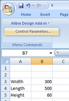
Every Geomagic Design installation includes an installation template which must be added to the Excel add-on list while running Excel once with administrator rights. Instructions as to how to do this with any supported version of Microsoft Office are available in the F1-help of Geomagic Design. Once properly installed, "Alibre Design Add-in" should be available from the Tools menu or Add-ins ribbon tab. Any numerical value cell may be selected to correspond to a Geomagic Design parameter, units specified and applied to a selected Geomagic Design file. For example we whip up something simple in Excel (shown right). Such a file can be created in Excel by anyone anywhere anytime (or it can be an imported CSV file etc)...

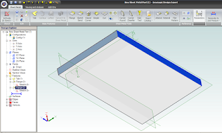
To update model parameters with the values listed in our spreadsheet, we need to start Geomagic Design and load the file in question. In our example we load the following basic Sheet Metal part, with overall parameters for "SM_length", "SM_width" and "SM_height":

 
Switching back over to our open spreadsheet, we select the Albre Design Add-in Control Parametrs (see above image of Excel). This opens a table in which cells are matched with parameter names:
 

To link spreadsheet values with model parameters, select an Active Session (model name currently open in Geomagic Design). All of the selected session's parameters will be listed by name. Now select the name of the desired model parameter from this list - and then the small "_" button down under Cell Reference and pick the workbook cell that you wish to link it to. Click the "Modify" button to finally change the parameter value to the one in the spreadsheet. Changes are shown immediately in Geomagic's active session model. Multiple changes can be made and applied at once by multi-selecting through the parameter list. If the spreadsheet is saved, the parameter links are saved with it.

To generate a DXF file of the final sheet metal design, a Geomagic drawing is used. Create a new Standard View. In the open Standard View Creation window, click the button "More Options". Check the option "Project as Flat Pattern" which will use the flattened version of the Sheet metal design for the projection view. Check that the projection scale is 1:1 and create the view. Once the flattened view is created, export the version of DXF which you require for CNC.

Geomagic Design is Australia's de facto low-cost 3D CAD alternative to SolidWorks and Autodesk Inventor. For more information about Geomagic Design or a free download, visit our website at http://www.caddit.net/cad-cam-software/geomagic.php

Google.